A datasheet gives you maximum figures. It never gives you a topology. An EasyBus3® system takes one Easy3-H, three Easy3-M and 384 Easy3-X, and two installations can meet that limit to the letter while having very little in common on site. It all comes down to a decision made very early on: where to put the masters.
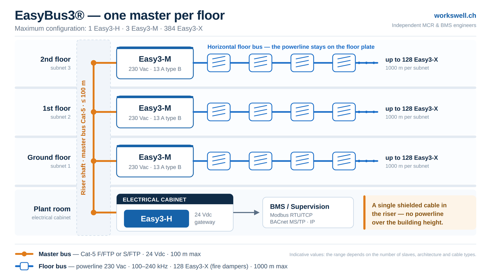
The usual reflex is to group the three Easy3-M in the electrical panel, next to the Easy3-H. It is compact and easy to read on a drawing. But it sends the three powerline subnets climbing the risers to collect the fire dampers floor by floor. The alternative we favour in this configuration is one master per floor: same hardware, same catalogue limit, a radically different installation.
Two bus levels, two media
What makes the trade-off possible is that the system layers two distinct networks. The master bus links the Easy3-H to its Easy3-M units over 24 Vdc on Cat-5 F/FTP or S/FTP cable, within a 100 m limit; the Easy3-H stays in the panel and provides the single gateway to the BMS (Modbus RTU/TCP, BACnet MS/TP or IP). The floor buses then link each Easy3-M to its Easy3-X devices by powerline over 230 Vac, in the 100–240 kHz band: up to 128 devices and 1000 m of cable run per subnet, power and control on the same pair of conductors.
The cable that goes up therefore does not have to be the cable that distributes. That is the designer’s entire margin of manoeuvre.
The structural benefit: no more bus in the risers
By placing each Easy3-M in its own floor cabinet, the powerline never leaves its floor plate and the riser carries nothing but a shielded network cable. Four consequences follow.
- The vertical copper shrinks. An EasyBus3® subnet requires a minimum of 3 × 2.5 mm² because it carries both power and signal; replacing it with Cat-5 reduces the cross-section, the conduit diameter to reserve and the pulling time.
- The 5 cm separation rule between cables becomes workable, because it now applies to a horizontal route rather than the most congested area of the building.
- EMC immunity moves into another category. The riser concentrates power feeders, variable-speed drives and lift machinery; running a 100–240 kHz signal through it means exposing the bus over the full height of the building.
- The length budget is spent on the floor. The 1000 m are no longer consumed by the climb, which leaves more signal margin and allows a denser distribution.
What the operator gains
A topology choice is really judged ten years later, when someone has to intervene. Each Easy3-M has its own 230 Vac supply and its own dedicated breaker, 13 A type B as a minimum: a trip or an intervention takes only one floor out of service, the other two subnets keep running. A communication fault is localised to a floor plate from the outset and is dealt with at the master concerned, without going back to the panel.
And because addressing follows the reality of the site (one master, one floor, one batch of 128 devices) damper testing and partial handovers can be phased floor by floor. Adding devices later affects neither the other subnets nor the vertical cabling.
The constraints to allow for
Check this first. The 100 m limit on the master bus is the sizing factor: the panel housing the Easy3-H must stay within 100 m of cable of the furthest Easy3-M. In a high-rise, that is the point to settle before any other discussion.
You also need a protected 230 Vac supply on each floor and space available for the Easy3-M in the cabinet: reservations to be made early, in coordination with the electrical package. Finally, the 1000 m per subnet remains an indicative value, varying with the number of slaves, the network architecture, the structure of the building and the cable types; it is up to the installer to size and guarantee the additional electrical components according to the constraints specific to the installation.
Nobody does this work for you
The manufacturer supplies hardware and limits. The installer builds what appears on the drawing handed to them. Between the two, someone has to decide where the masters go, verify that the 100 m holds from the chosen location, and weigh the compactness of a centralised layout against the robustness of a per-floor distribution.
That is the role of an independent engineering firm. We do not sell EasyBus3®: we have no interest in favouring one solution over another. What we bring is the analysis that turns a catalogue-compliant configuration into an installation that commissions without surprises and can be maintained without shutting down an entire building. We apply the same reasoning to a network topology, to the choice of an integration protocol or to the sizing of a control device: starting from the real building and how it is operated, never from the diagram that is easiest to draw.
A project involving a fire damper network, a BMS or an MCR refurbishment? That is exactly the kind of trade-off we handle in MCR design and planning. A first conversation is usually enough to define the potential and the scope of the assignment.